Masalah scale dapat menjadi salah satu penyebab menurunnya fluida produksi, hal ini karena scale yang terendapkan dapat memperkecil porositas dan permeabilitas batuan (formasi) produktif, disamping itu dapat juga mengganggu peralatan produksi dimana scale terendapkan dirangkaian itu.
Untuk alasan ini masalah scale harus dicegah dengan metode DSST. Apabila scale sudah terlanjur terbentuk, maka scale harus dibersihkan dulu dengan metode Acidizing.
Scale adalah endapan mineral yang terproduksi bersama air formasi yang karena reaksi kimia dan kondisi lingkungan yang mendukung, maka scale terendapkan.
A. Tempat Pengendapan Scale
Formasi produktif
Zona perforasi
Peralatan produksi bawah permukaan : gravel pack, screen liner, working barrel dan tubing produksi
Pipa alir di permukaan
Dan peralatan produksi lainnya
B. Kondisi Yang Mendukung Terjadinya Scale
Perubahan tekanan dan temperatur
Larutan lewat jenuh (supersaturated solution)
Terjadinya perubahan komposisi air formasi
Perubahan derajat keasaman (pH)
Bercampurnya air formasi dari lapisan yang berbeda
Dasar dari mekanisme scale inhibitor yakni usaha pencegahan sedini mungkin akan terjadinya scale dengan cara menginjeksikan bahan kimia ke dalam sumur untuk mencegah terjadinya reaksi kimia antara ion dan kation yang bisa mengendap. Jenis – jenis Scale Inhibitor yang memiliki kemampuan mencegah terjadinya Scale :
Phospate ester
Polymers (polyacramides)
Phosphonates
D. Faktor yang sangat penting dalam pemilihan inhibitor, sbb ;
Harga bahan kimianya
Kestabilan inhibitor terhadap perubahan tekanan dan temperatur yang besar
Keefektifannya
Kompabilitas terhadap fluida produksi, fluida workover / routine service dan bahan kimia lain
KANDIDAT PEMILIHAN SUMUR
1. Indikator
Penurunan jumlah cairan terproduksi secara drastis dapat menjadi indikator utama dalam mengidentifikasi terjadinya scaling di dalam suatu sumur produksi
Terjadinya perubahan tekanan dan temperatur yang tidak stabil
Nilai Scaling Indeks / Saturation Indeks dari hari pertama pengukuran water analysis dengan menggunakan metode, sbb ;
Diagram Stiff-Davis
OKSCALE (Oddo-Thompson)
Scalesoft
Urutan prioritas suatu sumur untuk di DSST, berdasarkan klasifikasi :
Sumur baru vertikal expansion --> perlu WA
Sumur setelah di acidizing (Acid Job) --> tidak perlu WA
Sumur setelah “revise liner” --> tidak perlu WA
Sumur commingle --> perlu WA
Preventive --> perlu WA
Re-DSST --> tidak perlu WA, pakai WA yang lama dan tidak perlu dilampirkan.
2. Pekerjaan Pendahuluan
Uji pH, jika pH < 6.5 tunda pekerjaan DSST
Uji Hardness (kandungan Ca dan Mg), jika Hardness > 300 ppm, tunda pekerjaan DSST
Check sumur dan lokasi, jika lokasi jelek, informasikan ke pumper
3. Pekerjaan Utama
Konfirmasi ke pumper area untuk memastikan seluruh fasilitas permukaan siap dijalankan
Adakan pertemuan tentang keselamatan kerja dengan seluruh crew yang terlibat dalam pekerjaan
Periksa seluruh hubungan antar valve, pasangan (connection) dan choke kepala sumur
Set pompa, tanki dan lakukan running test dengan mensirkulasikan fluida yang ada di dalam tanki.
Matikan sumur
Buat larutan mula-mula dengan jalan mencampurkan air bersih dengan demulsifier untuk membersihkan formasi, injeksikan air tersebut melalui annulus tanpa melampaui tekanan rekah formasi (300 psi)
Buat larutan scale inhibitor dengan mencampurkan scale inhibitor dengan air bersih. Injeksikan seluruh larutan scale inhibitor tersebut melalui annulus tanpa melampaui tekanan rekah formasinya (300 psi)
Buat larutan spacer / pengatur jarak dan injeksikan seluruh spacer tadi secepat mungkin tanpa melampaui tekanan formasi
Campurkan air bersih dengan demulsifier untuk melarutkan overflush (pembilas) yang berfungsi untuk mendesak larutan scale inhibitor sejauh 4 – 6 feet masuk secara mendatar ke dalam formasi
Matikan sumur antara 18 – 24 jam. Test pH dan Hardness. Jika pH < 6.5 atau Hardness > 300 ppm, tunda dulu POP dan segera informasikan ke pumper atau team leader
Kemudian jalankan kembali sumur produksinya (POP, Put well On Production)
Monitor PRC dan lakukan analisa air secara periodik hingga nilai PRC mendekati harga 2.19 ppm (biasanya antara 12 – 16 bulan) dan lakukan DSST ulang untuk treatment berikutnya
4. Kendala di Lapangan
Pompa yang digunakan kadang mengalami gangguan "masuk angin" sehingga pompa tidak bisa bekerja sebagaimana mestinya.
Adanya kebocoran disetiap persambungan pipa atau hose
Pada saat proses penginjeksian, fluida yang diinjeksikan keluar melalui cable submergible pump yang dikarenakan dougnut seal dalam kondisi kurang bagus
Jarak pengambilan air (biasanya dari Gathering Station) dari lokasi eksekusi yang terlalu jauh, sangat berpengaruh terhadap laju penginjeksian
Jika membutuhkan air yang banyak untuk digunakan sebagai campuran chemical kadang mengharuskan eksekutor menggunakan satu unit vacuum truck tambahan.
This chapter, entitled “Acidising and other Matrix Treatments”, discusses the chemical methods of well stimulation. The common factor among these treatments is that they are carried out under matrix conditions i.e. the injected fluids flow radially away from the wellbore since the treatment fluid is injected into the well at rates and pressures below that required for creation of a hydraulic fracture. This chapter mainly concentrates on the injection of acid (“Acidising”), the most frequently employed of the chemical treatments.
Matrix (stimulation) treatments are a common form of well intervention aimed at removing this formation damage and restoring the well to its natural, undamaged inflow performance. An alternative stimulation technique - propped hydraulic fracturing - will be covered in a later chapter. This latter well treatment can bypass this damage and/or increase the effective wellbore radius. Either of these stimulation treatments may be carried out immediately after drilling the well is completed or at any time in the well’s producing lifetime when they can be economically justified. Matrix stimulation treatments increase well productivity by pumping a specially formulated treatment fluid (frequently, but not always, an acid) which is designed to remove (normally dissolve) the formation damage. However, the keys to successful treatments are:
1)The identification of a suitable candidate well which is capable of a greater hydrocarbon production rate.
2)The selection of the optimum type of treatment fluid for the removal of the formation damage.
3)The design of the operational aspects of the treatment.
Ada ungkapan populer dalam dunia komputer yang menggambarkan pentingnya data dalam suatu simulasi, yaitu "GIGO : garbage in, garbage out". Persiapan data bertujuan untuk mendapatkan data yang valid dan sesuai kebutuhan didasarkan pada tujuan dan prioritas simulasi. Prosentase keakuratan hasil simulasi yang dilakukan, ditentukan oleh validitas data yang dipergunakan, sehingga tanpa data yang memadai gambaran yang diharapkan tidak akan tercipta atau bahkan akan memberikan informasi yang menyesatkan.
Data-data yang dibutuhkan untuk melakukan simulasi dapat diperoleh dari berbagai sumber data yang memungkinkan. Meskipun demikian, sebagian besar dari data tersebut tidak dapat langsung dipakai, tetapi memerlukan proses pengolahan sehingga dihasilkan data yang siap pakai. Pemilihan sumber data serta pengolahan juga sangat berpengaruh terhadap kesiapan data itu sendiri, yang pada alkhirnya juga berpengaruh terhadap hasil simulasi secara keseluruhan.
Operasi penyemenan merupakan bagian dari operasi pemboran yang memakan biaya yang besar karena peraatan yang digunakan tidak dapat dipakai kembali , karena tertanam dalam dalam sumur untuk seterusnya, seperti centralizer, casing dan scratcher. Penyemenan harus benar-benar sempurna dan tidak terjadi rongga-rongga pada tempat yang disemen sebabkan menyebabkan kerusakan casing akibat mengembangnya udara atau fluida lainnya yang masuk dalam rongga tersebut akibat terkena temperatur dan tekanan yang tinggi. Operasi penyemenan bertingkat (stage cementing) diterapkan apabila : Sumur terlalu dalam, Formasi diatas dan dibawah zona yang disemen cukup kompak dan jauh, dan Untuk menghindari tekanan pompa yang berlebihan, sehingga dapay mengurangi pengeluaran biaya.
Penyemenan suatu sumur merupakan salah satu faktor yang tidak kalah pentingnya dalam suatu operasi pemboran. Berhasil atau tidaknya suatu pemboran, salah satu diantaranya adalah tergantung dari berhasil atau tidaknya penyemenan sumur tersebut.
Penyemenan sumur secara integral, merupakan salah satu aspek yang sangat penting dalam suatu operasi pemboran, baik sumur minyak maupun gas. Semen ter-sebut digunakan untuk melekatkan rangkaian pipa selubung dan mengisolasi zona produksi serta mengantisipasi adanya berbagai masalah pemboran.
Perencanaan penyemenan meliputi :
·Perkiraan kondisi sumur (ukuran, tem-peratur, tekanan, dsb.)
·Penilaian terhadap sifat lumpur pem-boran
·Pembuatan suspensi semen (slurry de-sign)
·Teknik penempatan
·Pemilihan peralatan, seperti centralizers, scratchers, dan float equipment
Program perencanaan penyemenan secara tepat, merupakan hal pokok yang akan mendukung suksesnya operasi pemboran.
Pada dasarnya operasi penyemenan bertujuan untuk :
1.Melekatkan pipa selubung pada dinding lubang sumur,
2.Melindungi pipa selubung dari masalah-masalah mekanis sewaktu operasi pem-boran (seperti getaran),
3.Melindungi pipa selubung dari fluida formasi yang bersifat korosi, dan
4.Memisahkan zona yang satu terhadap zona yang lain dibelakang pipa selu-bung.
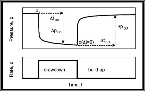
Drill-stem testing provides a method of temporarily completing a well to determine the productive characteristics of a specific zone. As originally conceived, a drill-stem test provided primarily an indication of formation content. The pressure chart was available, but served mainly to evaluate tool operation. Currently, analysis of pressure data in a properly planned and executed DST can provide, at reasonable cost, good data to help evaluate the productivity of the zone, the completion practices, the extent of formation damage and perhaps the need for stimulation. A drill-stem test provides an estimate of formation properties and wellbore damage. These data may be used to determine the well's flow potential with a regular completion that uses stimulation techniques to remove damage and increase effective wellbore size.
Reservoir characteristics that may be estimated from DST analysis include:
·Average effective permeability. This may be better than core permeability since much greater volume is averaged. Also, effective permeability rather than absolute permeability is obtained.
·Reservoir pressure: Measured, if shut-in time is sufficient, or calculated, if not.
·Wellbore damage: Damage ratio method permits the estimation of what the well should make without damage.
·Barriers, permeability changes, and fluid contacts: These reservoir anomalies affect the slope of the pressure buildup plot. They usually require substantiating data to differentiate one from the other.
·Radius of investigation: An estimate of how far away from the wellbore the DST can "see".
·Depletion: Can be detected if the reservoir is small and the test is properly run.
Treatment fluid selection in sandstone formations is highly dependent on the mineralogy of the rock as well as the damage mechanism. Hydrofluoric (HF) acid is typically used to dissolve the damaging silicate particles. Nonacid systems are sometimes used to disperse whole mud and allow it to be produced with the treating fluid. The criteria for selecting the treating fluid are mineralogy, formation damage mechanism, petrophysics and well conditions.
Formation mineralogy
Compatibility and sensitivity
Compatibility of the formation minerals to the various treating fluids and their additives is a significant issue when selecting fluids for acidizing. Compatibility implies that permeability does not decrease when the treating fluid contacts the formation. This concept of compatibility applies especially to sandstones, where potentially damaging reactions may occur.
Compatibility and sensitivity are related concepts. As stated by McLeod (1984), a successful matrix treatment depends on the favorable response of the formation to the treatment fluid. The treating fluid, therefore, must remove existing damage without creating additional damage through interactions with the formation rock or fluids. A formation is sensitive if the reaction between the rock minerals and a given fluid induces damage to the formation.
The sensitivity of a formation to a given fluid includes all the detrimental reactions that can take place when this fluid contacts the rock. These detrimental reactions include the deconsolidation and collapse of the matrix, the release of fines or the formation of precipitates. The precipitation of some damaging compounds cannot be avoided. Treating and overflush fluid stages are sized; so, there is sufficient volume to push potential precipitates deep enough into the reservoir to minimize their effects because of the logarithmic relationships between pressure drop and distance from the wellbore.
Sandstones can be sensitive to acid depending on temperature and mineralogy. Ions of silicon, aluminum, potassium, sodium, magnesium and calcium react with acid and can form precipitates at downhole temperatures, once their solubility product is exceeded. If these precipitates occur in the near wellbore area, they can damage the formation. Sensitivity depends on the overall reactivity of the formation minerals with the acid. Reactivity depends on the structure of the rock and the distribution of minerals within the rock, i.e., the probability of the acid reaching the soluble minerals.
The sensitivity of sandstone will also depend on the permeability of the formation. Lowpermeability sandstones are more sensitive than high-permeability sandstones for a given mineralogy. Acid formulations should be optimized on the basis of a detailed formation evaluation (Davies et al., 1992, Nitters and Hagelaars, 1990).
Well Completion adalah pekerjaan tahap akhir atau pekerjaan penyempurnaan untuk mempersiapkan suatu sumur pemboran menjadi sumur produksi. Untuk mendapatkan hasil produksi yang optimum dan mengatasi efek negatif dari setiap lapisan produktif maka harus dilakukan pemilihan metode well completion yang tepat dan ukuran peralatan yang sesuai untuk setiap sumur. Tidak ada dua jenis well completion yang sama persis antara sumur satu dengan yang lainnya, tetapi selalu bervariasi tergantung dari faktor yang dipertimbangkan. Tujuan dari well completion adalah mengatur aliran fluida dari formasi produktif dasar sumur ke permukaan sebaik mungkin.
Jenis-Jenis Formation Completion
Metoda well completion terbagi atas tiga bagian utama, yaitu bottom hole (formation) completion, tubing completion dan wellhead completion. Bottom hole completion dapat dilakukan secara open hole completion, perforated casing completion dan liner completion.
Pada tubing completion diusahakan agar mampu mengangkat fluida yang telah berada dalam lubang sumur ke permukaan dengan semaksimal mungkin. Tubing completion berdasarkan jumlah production string yang digunakan dalam satu sumur, dibedakan menjadi tiga jenis, yaitu single completion, commingle completion, dan multiple completion.
Wellhead completion dimaksudkan untuk memberikan keselamatan kerja pada waktu penggantian atau pemasangan peralatan produksi dibawah permukaan dan juga berfungsi untuk mengontrol aliran fluida dari sumur.
Dari semua jenis tipe komplesi secara umum, adapun halnya yang akan dibahas lebih terperinci hanya Bottom hole (Formation) Completion.
Gas merupakan suatu fluida yang homogen dengan densitas dan viskositas rendah serta tidak tergantung pada bentuk tempat yang ditempatinya, sehingga dapat mengisi semua ruangan yang ada. Berdasarkan jenisnya, gas dapat dibedakan menjadi dua, yaitu gas ideal dan gas nyata.
Gas ideal, adalah fluida dimana :
·Mempunyai molekul yang dapat diabaikan bila dibandingkan dengan volume fluida keseluruhan.
·Tidak mempunyai tenaga tarik-menarik maupun tolak-menolak antar molekul-molekulnya, atau antara molekul-molekul dengan dinding wadahnya.
·Tumbukan antar molekul-molekulnya bersifat lenting sempurna, sehingga tidak terjadi kehilangan tenaga akibat tumbukan tersebut.
Well Logging merupakan pekerjaan penilaian formasi pada saat pemboran (LWD), sebelum di casing (Open Hole) ataupun setelah dicasing (Case Hole) dengan cara menurunkan serangkain alat pendeteksi sifat – sifat fisik batuan melalui wireline ataupun batang bor (drill string) ke kedalaman yang akan diinvestigasi. Diameter peralatan logging convensional umumnya 3 5/8’’, dengan panjang tool logging 20 – 50 ft. Peralatan ini di turunkan kedasar lubang bor dengan menggunakan wireline cable yang dilengkapi 7 conduktor (2 konduktor untuk mengirim arus dari permukaan ke logging tool di bawah permukaan, dan 5 konduktor mentransmisi data dari peralatan logging bawah permukaan ke ruang kontrol) (lihat gambar 3.46). Tetapi untuk Logging While Drilling (LWD) peralatan dirangkai pada rangkaian pemboran yang dilengkapi dengan peralatan logging, memori, dan batrai dalam melakukan penilaian formasi saat pemboran. Beberapa log yang dihasilkan dari pengukuran formasi berdasarkan fungsinya, yaitu :
Penilaian formasi juga dilakukan setelah proses pemboran dan komplesi selesai serta pada saat produksi. Hal ini dilakukan bertujuan untuk mendapatkan data yang lebih komplit tentang reservoir. Kegiatan penilaian formasi yang dilakukan setelah proses pemboran dan komplesi atau pada saat produksi terdiri dari well testing, PVT analysis, dan Production Test.
Well Testing
Tujuan utama dari uji sumur yaitu untuk mengukur kemampuan formasi dalam memproduksikan fluida yang dikandungnya atau dengan kata lain mengukur produktivitas formasi. Prinsip dasar pengukuran adalah membuat perbedaan tekanan antara formasi dengan lubang bor. Perencanaan, pengoperasian dan analisa hasil uji sumur yang tepat akan membantu melengkapi data tentang permeabilitas, derajat kerusakan sumur, tekanan reservoar, kemungkinan batas–batas reservoar dan heterogenitas formasi.
Metode well testing dapat dibagi menjadi 5 macam, yaitu :
Tiap-tiap jenis komplesi sumur mempunyai fungsi yang berbeda-beda sehingga faktor-faktor yang mempengaruhi pemilihan jenis komplesi sumur juga berbeda.
1. Kekompakan Batuan
Kekompakan batuan merupakan salah satu dasar pemilihan jenis formation completion sehubungan dengan pencegahan keguguran formasi dan terproduksinya pasir. Adapun analisa kondisi formasi dan parameter peralatan yang digunakan untuk perhitungan dalam pemilihan metode penyelesaian sumur meliputi : kestabilan formasi, butir pasir dan ukuran celah (lubang screen liner). Untuk analisa kestabilan formasi dan analisa butiran pasir diperlukan data logging dan coring dari lapisan produktif yang akan diproduksikan, sedangkan ukuran lubang screen liner dipilih berdasarkan besarnya fluida reservoir yang diinginkan untuk mengalir ke dalam sumur.
Kekompakan batuan dapat diperkirakan dari faktor sementasi yang diberikan dari persamaan Archie, yaitu :
CMG (Computer Modelling Group) 2002.10adalah program simulasi reservoir yang dibuat oleh Computer Modelling Group Ltd., Calgary, Canada. Program simulasi ini digunakan untuk melakukan simulasi reservoir. Program ini dapat digunakan untuk reservoir satu fasa, dua atau multi fasa dan juga dapat digunakan untuk membuat simulasi dengan dua dimensi atau tiga dimensi. CMG memiliki tiga jenis simulator yaitu IMEX, GEM, dan STARS.
Simulator IMEX digunakan untuk kondisi isothermal, aliran simultan dari minyak, gas dan air yang berhubungan dengan viskositas, gaya gravitasi dan gaya kapiler. Istilah Black Oil melambangkan bahwa fasa hidrokarbon dipandang sebagai satu jenis cairan homogen dan tidak ditinjau dari komposisi kimianya. Komposisi fasa dianggap konstan walaupun kelarutan gas dalam minyak dan air diperhitungkan.
Simulator GEM digunakan untuk simulasi reservoir dengan jenis compositional dimana komposisi cairan atau gas diperhitungkan terhadap perubahan tekanan. Simulasi jenis ini banyak digunakan untuk studi perilaku reservoir yang berisi volatile-oil dan gas condensate.
Simulator STARS digunakan untuk studi aliran fluida, perpindahan panas maupun reaksi kimia. Simulasi ini juga banyak digunakan untuk studi injeksi uap panas (steam flood) dan pada proses perolehan minyak tahap lanjut dengan metode in-situ combution.
Pada simulator CMG juga terdapat simulator WINPROP yaitu equation of state untuk multifasa. WINPROP dapat digunakan untuk menganalisa kelakuan fasa fluida reservoir pada sistem gas dan juga minyak, dan digunakan untuk membuat properti komponen untuk simulator komposisional GEM, simulator Black Oil IMEX, dan simulator thermal STARS. WINPROP biasanya digunakan dalam pembuatan properti komponen yang akan digunakan sebagai data input pada simulator komposisional GEM.
Secara garis besar program simulasi pada CMG terdiri dari tujuh bagian utama, yaitu : Technologies Launcher, ModelBuilder, GridBuilder, Simulator (IMEX, GEM, STARS), Results Graph dan Results 3D. Berikut ini akan dijelaskan secara ringkas tentang fungsi dari masing-masing bagian simulator.
Minyak bumi adalah suatu senyawa hidrokarbon yang terdiri dari karbon (83-87%), hidrogen (11-14%), nitrogen (0,2-0,5%), sulfur (0-6%), dan oksigen (0-3,5%). Proses produksi minyak dari formasi tersebut mempunyai kandungan air yang sangat besar, bahkan bisa mencapai kadar lebih dari 90%. Selain air, juga terdapat komponen-komponen lain berupa pasir, garam-garam mineral, aspal, gas CO2 dan H2S. Komponen-komponen yang terbawa bersama minyak ini menimbulkan permasalahan tersendiri pada proses produksi minyak bumi.
Air yang terdapat dalam jumlah besar sebagian dapat menimbulkan emulsi dengan minyak akibat adanya emulsifying agent dan pengadukan. Selain itu hal yang tak kalah penting ialah adanya gas CO2 dan H2S yang dapat menyebabkan korosi dan dapat mengakibatkan kerusakan pada casing, tubing, sistem perpipaan dan surface fasilities.
Sedangkan ion-ion yang larut dalam air seperti kalsium, karbonat, dan sulfat dapat membentuk kerak (scale). Scale dapat menyebabkan pressure drop karena terjadinya penyempitan pada sistem perpipaan, tubing, dan casing sehingga dapat menurunkan produksi.
Korosi adalah suatu proses elektrokimia dimana atom-atom akan bereaksi dengan zat asam dan membentuk ion-ion positif (kation). Hal ini akan menyebabkan timbulnya aliran-aliran elektron dari suatu tempat ke tempat yang lain pada permukaan metal.
Istilah scale dipergunakan secara luas untuk deposit keras yang terbentuk pada peralatan yang kontak atau berada dalam air.
Dalam operasi produksi minyak bumi sering ditemui mineral scale seperti CaSO4, FeCO3, CaCO3, dan MgSO4. Senyawa-senyawa ini dapat larut dalam air.
Scale CaCO3 paling sering ditemui pada operasi produksi minyak bumi. Akibat dari pembentukan scale pada operasi produksi minyak bumi adalah berkurangnya produktivitas sumur akibat tersumbatnya penorasi, pompa, valve, dan fitting serta aliran. Penyebab terbentuknya deposit scale adalah terdapatnya senyawa-senyawa tersebut dalam air dengan jumlah yang melebihi kelarutannya pada keadaan kesetimbangan. Faktor utama yang berpengaruh besar pada kelarutan senyawa-senyawa pembentuk scale ini adalah kondisi fisik (tekanan, temperatur, konsentrasi ion-ion lain dan gas terlarut).
Sasaran pemboran horizontal adalah membuat lubang horizontal dengan pertambahan sudut tertentu dari titik belok pertama. Masalah utama timbul karena adanya bagian pertambahan sudut dari bagian horizontal, yang berhubungan dengan efek gravitasi, friksi dan pengendapan partikel (cutting) pemboran. Masalah-masalah dalam pemboran horizontal diantaranya :
1)Problem terhadap rangkaian, yaitu torsi, drag, buckling dan tension.
2)Problem lumpur dan hidrolika, yaitu pengendapan cutting dan gugurnya dinding lubang sumur.
3)Kecenderungan penyimpangan sudut.
4)Rendahnya laju penembusan.
5)Differential pipe sticking.
Perencanaan rangkaian pipa bor yang akan dipergunakan harus mempertimbangkan beban drag, beban torsi, buckling, dan tension. Dalam hal ini yang akan kita bicarakan adalah masalah kekuatan dan beban dari rangkaian pipa bor.
Pembelokan lubang bor dalam pemboran horizontal dilakukan dengan besar sudut kemiringan dan arah tertentu sesuai dengan type pemboran horizontal yang dipilih. Pembelokan lubang bor dimulai dari KOP hingga target arah yang diinginkan (EOC/End Of Curvature), pembelokan arah diusahakan agar tidak mengalami penyimpangan terhadap rencana/ target, yang saat ini dikontrol melalui peralatan Measurement While Drilling (MWD).
Lost circulation has been one of the major challenges that cause much nonproductive rig time each year. With recent advances, curing lost circulation has migrated from “plugging a hole” to “borehole strengthening” that involves more rock mechanics and engineering. These advances have improved the industry’s understanding of mechanisms that can eventually be translated into better solutions and higher success rates. This paper provides a review of the current status of the approaches and a further understanding on some controversial points.
There are two general approaches to lost circulation solutions : proactive and corrective, based on whether lost circulation has occurred or not at the time of the application. This paper provides a review of both approaches and discusses the pros and cons related to different methods—from an understanding of rock mechanics and operational challenges.
Introduction
Lost circulation (LC) is defined as the loss of whole mud (e.g.,solids and liquids) into the formation (Messenger 1981). There are two distinguishable categories of losses derived from its leakoff flowpath: Natural and Artificial. Natural lost circulation occurs when drilling operations penetrate formations with large pores, vugs, leaky faults, natural fractures, etc. Artificial lost circulation occurs when pressure exerted at the wellbore exceeds the maximum the wellbore can contain. In this case, hydraulic fractures are
generally created.
During the last century, lost circulation presented great challenges to the petroleum industry, causing significant expenditure of cash and time in fighting the problem. Trouble costs have continued into this century for mud losses, wasted rig time, and ineffective remediation materials and techniques. In worst cases, these losses can also include costs for lost holes, sidetracks, bypassed reserves, abandoned wells, relief wells, and lost petroleum reserves.
The risk of drilling wells in areas known to contain these problematic formations is a key factor in decisions to approve or cancel exploration and development projects.
Reservoir memberikan tekanan fluida dengan mengendalikan tenaga untuk mendorong fluida menuju lubang bor, dalam aliran sumur natural, mengimbangi tubing produksi ke permukaan. Untuk memaksimalkan kapasitas produksi dari sumur terpisah, memastikan dengan tepat ada pembatasan minimal di flowline. Bagaimanapun, dalam kasus yang serupa, dari sistem kapasitas produksi akan terus-menerus menyesuaikan dalam line dengan gangguan aliran lainnya atau ketidakstabilan dalam sumur. Jadi, sebagian besar sumur produksi menggunakan choke atau pembatasan flowline downstream dari kepala sumur ke tekanan balik dari sumur.
Pelaksanaan menutup tekanan balik dari flowline ke kepala sumur mungkin perlu untuk beberapa alasan berikut :
·Mempertahankan aliran stabil/keadaan tekanan downstream dari choke.
·Mengendalikan drawdown di sumur dan karena itu kejadian terbatas dari cusping gas atau water coning sampai lubang bor atau kegagalan sekitar formasi di lubang bor.
·Mengurangi turunnya fluktuasi di sumur yang berubah-ubah oleh tekanan balik dari sistem yang diterapkan.
·Memisahkan fluktuasi tekanan dari sumur yang di buat dalam sistem proses, gathering dan transportasi.
A drill string on an drilling rig is a column, or string, of drill pipe that transmits drilling fluid (via the mud pumps) and rotational power (via the kelly drive or top drive) to the drill bit. The term is loosely applied as the assembled collection of the drill pipe, drill collars, tools and drill bit. The drill string is hollow so that drilling fluid can be pumped down through it and circulated back up the annulus (void between the drill string and the formation).
Drill string components
The drill string is typically made up of 4 sections:
Bottom hole assembly (BHA)
Transition pipe, which is often heavyweight drill pipe (HWDP)
Drill pipe
Drill stem subs
Each section is made up of several components, joined together using special threaded connections known as tool joints.
Bottom hole assembly (BHA)
The BHA is made up of a drill bit which is used to break-up the rock formations, drill collars which are heavy, thick-walled tubulars used to apply weight to the drill bit, and stabilizers which keep the drilling assembly centered in the hole. The BHA may also contain other components such as a downhole motor, Rotary Steerable System, measurement while drilling (MWD), and logging while drilling (LWD) tools.
Transition pipe
Heavyweight drill pipe (HWDP) is used to make the transition between the drill collars and drill pipe. The function of the HWDP is to provide a flexible transition between the drill collars and the drill pipe. This helps to reduce the number of fatigue failures seen directly above the BHA. A secondary use of HWDP is to add additional weight to the drill bit.
Drill pipe
Drill pipe makes up the majority of a drill string. A drill string is typically about 15,000 feet (4.6 km) long for an oil or gas well vertically drilled onshore in the United States and may extend to over 30,000 feet (9.1 km) for an offshore deviated (non-vertical) well.
Drill stem subs
Drill stem subs are used to connect drill string elements.
Running a drill string
Most components in a drill string are manufactured in 31 foot lengths (range 2) although they can also be manufactured in 45 foot lengths (range 3). Each 31 foot component is referred to as a joint. Typically 2, 3 or 4 joints are joined together to make a stand.
Pulling the drill string out of or running the drill string into the hole is referred to as tripping. Drill pipe, HWDP and collars are typically tripped in stands to save time.
Stuck drill string
A stuck drill string can be caused by many situations.
Packing-off due to cuttings settling back into the wellbore when circulation is stopped.
Differentially when the formation pressure is too low, the wellbore pressure is too high or both, essentially pushing the pipe onto the wall of the wellbore.
Keyhole sticking occurs mechanically as a result of pulling up into doglegs when tripping.
Adhesion due to not moving it for a significant amount of time.
Once the tubular member is stuck, there are many techniques used to extract the pipe. The tools and expertise are normally supplied by an oilfield service company. Two popular tools and techniques are the oilfield jar and the surface resonant vibrator. Below is a history of these tools along with how they operate.
History of Jars
The mechanical success of cable tool drilling has greatly depended on a device called jars, invented by a spring pole driller, William Morris, in the salt well days of the 1830's. Little is known about Morris except for his invention and that he listed Kanawha County (now in West Virginia) as his address. Morris patented this unique tool in 1841 for artesian well drilling. Later, using jars, the cable tool system was able to efficiently meet the demands of drilling wells for oil.
The jars were improved over time, especially at the hands of the oil drillers, and reached the most useful and workable design by the 1870's, due to another patent in 1868 by Edward Guillod of Titusville, Pennsylvania, which addressed the use of steel on the jars' surfaces that were subject to the greatest wear. Many years later, in the 1930's, very strong steel alloy jars were made.
A set of jars consisted of two interlocking links which could telescope. In 1880 they had a play of about 13 inches such that the upper link could be lifted 13 inches before the lower link was engaged. This engagement occurred when the cross-heads came together.Today, there are two primary types, hydraulic and mechanical jars. While their respective designs are quite different, their operation is similar. Energy is stored in the drillstring and suddenly released by the jar when it fires. Jars can be designed to strike up, down, or both. In the case of jarring up above a stuck bottomhole assembly, the driller slowly pulls up on the drillstring but the BHA does not move. Since the top of the drillstring is moving up, this means that the drillstring itself is stretching and storing energy. When the jars reach their firing point, they suddenly allow one section of the jar to move axially relative to a second, being pulled up rapidly in much the same way that one end of a stretched spring moves when released. After a few inches of movement, this moving section slams into a steel shoulder, imparting an impact load.
In addition to the mechanical and hydraulic versions, jars are classified as drilling jars or fishing jars. The operation of the two types is similar, and both deliver approximately the same impact blow, but the drilling jar is built such that it can better withstand the rotary and vibrational loading associated with drilling. Jars are designed to be reset by simple string manipulation and are capable of repeated operation or firing before being recovered from the well. Jarring effectiveness is determined by how rapidly you can impact weight into the jars. When jarring without a compounder or accelerator you rely only on pipe stretch to lift the drill collars upwards after the jar releases to create the upwards impact in the jar. This accelerated upward movement will often be reduced by the friction of the working string along the sides of the well bore, reducing the speed of upwards movement of the drill collars which impact into the jar. At shallow depths jar impact is not achieved because of lack of pipe stretch in the working string.
When pipe stretch alone cannot provide enough energy to free a fish, compounders or accelerators are used. Compounders or accelerators are energized when you over pull on the working string and compress a compressible fluid through a few feet of stroke distance and at the same time activate the fishing jar. When the fishing jar releases the stored energy in the compounder/acclerator lifts the drill collars upwards at a high rate of speed creating a high impact in the jar.
System Dynamics of Jars
Jars rely on the principle of stretching a pipe to build elastic potential energy such that when the jar trips it relies on the masses of the drill pipe and collars to gain velocity and subsequently strike the anvil section of jar. This impact results in a force, or blow, which is converted into energy.
The concept of using vibration to free stuck objects from a wellbore originated in the 1940's, and probably stemmed from the 1930's use of vibration to drive piling in the Soviet Union. The early use of vibration for driving and extracting piles was confined to low frequency operation; that is, frequencies less than the fundamental resonant frequency of the system and consequently, although effective, the process was only an improvement on conventional hammer equipment. Early patents and teaching attempted to explain the process and mechanism involved, but lacked a certain degree of sophistication. In 1961, A. G. Bodine obtained United States Patent 2,972,3801[1] that was to become the "mother patent" for oil field tubular extraction using sonic techniques. Mr. Bodine introduced the concept of resonantvibration that effectively eliminated the reactance portion of mechanical impedance, thus leading to the means of efficient sonic power transmission. Subsequently, Mr. Bodine obtained additional patents directed to more focused applications of the technology.
The first published work on this technique was outlined in a 1987 Society of Petroleum Engineers (SPE) paper presented at the International Association of Drilling Contractors in Dallas, Texas [2] detailing the nature of the work and the operational results that were achieved. The cited work involving liner, tubing, and drill pipe extraction and was very successful. Reference Two[3] presented at the Society of Petroleum Engineers Annual Technical Conference and Exhibition in Aneheim, Ca, November, 2007 explains the resonantvibration theory in more detail as well as its use in extracting long lengths of mud stuck tubulars. The Figure 1 below shows the components of a typical surface resonant vibrator.
Surface Resonant Vibrators rely on the principle of counter rotating eccentric weights to impart a sinusoidalharmonic motion from the surface into the work string at the surface. Reference Three (above) provides a full explanation of this technology. The frequency of rotation, and hence vibration of the pipe string, is tuned to the resonant frequency of the system. The system is defined as the surface resonant vibrator, pipe string, fish and retaining media. The resultant forces imparted to the fish is based on the following logic:
The delivery forces from the surface are a result of the static overpull force from the rig, plus the dynamic force component of the rotating eccentric weights
Depending on the static overpull force component, the resultant force at the fish can be either tension or compression due to the sinusoidal force wave component from the oscillator
Initially during startup of a vibrator, some force is necessary to lift and lower the entire load mass of the system. When the vibrator tunes to the resonant frequency of the system, the reactive load impedance cancels out to zero by virtue of the inductance reactance (mass of the system) equalling the compliance or stiffness reactance (elasticity of the tubular). The remaining impedance of the system, known as the resistive load impedance, is what is retaining the stuck pipe.
A phenomenon known as fluidization of soil grains takes place during resonantvibration whereby the granular material constraining the stuck pipe is transformed into a fluidic state that offers little resistance to movement of bodies through the media. In effect, it takes on the characteristics and properties of a liquid.
During pipe vibration, Dilation and Contraction of the pipe body, known as Poisson’s ratio, takes place such that that when the stuck pipe is subjected to axial strain due to stretching, its diameter will contract. Similarly, when the length of pipe is compressed, its diameter will expand. Since a length of pipe undergoing vibration experiences alternate tensile and compressive forces as waves along its longitudinal axis (and therefore longitudinal strains), its diameter will expand and contract in unison with the applied tensile and compressive waves. This means that for alternate moments during a vibration cycle the pipe may actually be physically free of its bond.


 6/08/2011 03:49:00 PM
 Victor Manik


 Posted in:


